XLTRC2 SOFTWARE
WHAT IS XLTRC2?
XLTRC2 is a suite of very fast, accurate and experimentally verified, and user-friendly codes for executing a complete lateral and torsional rotordynamic analysis of rotating machinery including pumps, compressors and turbines. Extensive help files are provided for the base and support-library codes. SI or US units can be used interchangeably. XLTRC2 is bundled with no less than twenty five examples of rotordynamic analysis including rotors for compressors, pumps and gas turbines, each model featuring distinctive bearing/seal support conditions and displaying unique characteristics of rotordynamic behavior.
XLTRC2 runs on Windows XP, Vista and Win7, and Microsoft Excel 2003, 2007 and 2010 versions. XLTRC2 also runs on 64-bit Windows operation systems, while maintaining backward compatibility with older systems.
HOW DOES XLTRC2 WORK?
For lateral rotordynamics, XLTRC2 uses a Timoshenko beam, finite-element formulation to model the rotor and housing elements to any degree of accuracy that the analyst feels appropriate. Model dimensionality and execution time are dramatically reduced by using real, zero-running speed modes in a component-mode synthesis formulation. By using real modes (instead of complex modes) the initial modal calculation time is minimized (dramatically), and interpolation and extrapolation of modal parameters is eliminated.Constraint modes are used only at bearing locations and connection points that require nonlinear or frequency-dependent force or moment impedances. XLTRC2 generates rotordynamic results faster than most experienced engineers can input data and evaluate results. Stated differently, engineers don’t wait on XLTRC2.
WHAT ADVANCED FEATURES DOES XLTRC2 PROVIDE?
The following capabilities and features are provided for lateral rotordynamic analysis:
• Steady state rotor response due to base harmonic motion. This feature allows calculation of steady state rotor response of a rotor due to motion of an off-shore oil platform, for example.
• Multi-rotor/housing models can be easily developed including dual-rotor “shaft-in-shaft” systems.
• Housings that are not adequately modeled by a beam model can be modeled directly by ANSYS, and the resultant component-mode output directly loaded into XLTRC2 for analysis.
• General linear transfer-function matrices can be used directly to model reaction elements versus (shaft speed dependent) stiffness and damping coefficients: e.g., the transfer function of a magnetic bearing is readily and directly accepted. Force (2×2) and combined force and moment (2×2) transfermatrices are accepted.
• Reaction-load/motion transfer-functions are accepted with sensor measurements of motion at one location and force application at another location.
• The influence of bearings and seal misalignments can be directly modeled. For a statically indeterminate rotor, a bearing or seal can be arbitrarily misaligned, changing the bearing loads and (for a hydrodynamic bearing) changing the rotordynamic coefficients and response.
• Rotor Response due to bent-shaft excitation.
• Rotor response and housing acceleration levels due to base excitation. This feature can be used to easily calculate relative rotor response and housing acceleration levels for a compressor on a moving off-shore platform.
• Rotor response can be calculated due to prescribed base maneuver motion. This feature can be used to calculate rotor deflections and bearing loads of aircraft gas turbine rotors due to the mass-center acceleration and pitch, yaw, and roll of the aircraft.
• Bending stresses can be calculated using the bending moments and the shaft sectional modulus. Three maximum bending stresses are reported corresponding to static load, forward whirl imbalance loading and reverse whirl imbalance loading.
• A time-transient nonlinear feature is available to analyze the influence of nonlinearities such as bearing dead bands, rubbing, hydrodynamic cylindrical journal bearings and squeeze film dampers, etc. Blade loss phenomena, limit-cycle motion of vertical pumps, etc. can be analyzed. An automated time transient response calculation tool helps to perform multiple cases at one time.
• User-defined nonlinear connections can be handled using user defined DLLs (dynamic linked libraries).
• External torques, constant or time varying, can be specified for each shaft to simulate transient shaft motions during start-up and run-down. Responses to (sudden) imbalances can be readily obtained for rotors supported on fluid.
• Undamped and damped torsional frequencies can be calculated. Concentrated damping can be specified at bearings as well as shaft damping. Bearing damping is from a rotor station to ground. Shaft damping arises from relative station motion along the shaft.
• Torsional interference diagrams (Campbell diagram) can be easily created once the undamped (or damped) torsional frequencies are calculated. The line frequencies (usually 60 Hz in USA or 50 Hz in
Europe) are used to calculate the slip line speed. A straight line is drawn in the diagram connecting the twice slip line speed (y-axis) to the rotor synchronous speed (x-axis).The torsional frequencies are plotted on the same graph to form a Campbell type diagram.
• Torsional forced (steady-state) response is similar to imbalance response calculation in the lateral analysis.
• Four different motor torque input and output options are available:
(a) Synchronous motor with drive torque and pulsating torque input as a function of speed,
(b) Synchronous motor with drive torque, pulsating torque and arbitrary pulsating frequency, and
(c) Load torque, i.e., input of load torque as a function of speed.
• Torque inputs are used for a startup transient response analysis. The drive and load torques are specified at different stations by assigning them as one of the available types of motor torque inputs.
• Once the data on variation of torque vs. time are available, the user can perform a Cumulative Fatigue Analysis (predicted number of starts the machine will survive).
ONE TOUCH API 684 REPORTING
Because of the extensive research conducted in the Turbo- Lab (TL), and the close contact of the TL with industry through the Turbomachinery
Research Consortium, XLTRC2 is being continually upgraded. A recent major update was the API module. This module greatly facilitates the day-today job of the rotordynamics analyst, saving valuable time in preparing API reports. The repetitive tasks of defining and running all the different combinations of imbalance, bearing coefficients, and aerodynamic cross coupling that are required by the API standards are now automated.
Experienced users of XLTRC2 have found this module to be a great help in accelerating the design process and in producing standardizing API reports.
The API module is an Excel add-in. An additional toolbar enables the user to define and run all API standards.
With minimum user inputs and instructions, the response analysis let you define different cases of imbalance and bearing coefficients. The module then loops through the cases and shows the response results with all the margins specified and vibration limits checked against the API standards. The user can also specify stations to check for potential rubbing, clearances, and bearing-probe responses, and also run Undamped Critical Speed (UCS) analyses where the output is specifically tailored for API reports.
The API module lets the User define the parameters to run level I and II stability analyses. In level I, the user can specify bearing coefficients and cross coupled aerodynamic destabilizing force levels. The results will show the log decrement and stability regions of the system.
SUPPORTING LIBRARY CODES
The base rotordynamics codes provide the strong skeleton for an accurate and efficient structural dynamic rotor and housing model. However, accurate rotor dynamics analysis for real turbomachinery units also requires careful modeling of support bearings, seals, squeeze-film dampers, etc. XLTRC2 provides an unmatched support library to define the dynamic reaction forces developed by these elements. A brief summary of these support codes is provided below. Excel Graphical user interfaces (GUIs) to FORTRAN executable codes. US and SI unit versions are available for each GUI.
LIQUID LUBRICATED HYDRODYNAMIC AND HYDROSTATIC JOURNAL BEARINGS
Codes predict the forced performance of fluid film lubricated journal bearings for rotor lateral support. For a User specified geometry, fluid properties and operating conditions (load and shaft speed), a code calculates the operating journal eccentricity, flow rate, drag torque, power loss and temperature rise, and (2×2) stiffness and damping rotordynamic force coefficients. Additional features include the display of the film, pressure and temperature fields; and where applicable, calculation of added mass coefficients. Predictions from codes validated against test data acquired at TAMU Turbomachinery Laboratory or in the archival literature.
XLJRNL a computer implementation of Someya’s Journal-Bearing DataBook, calculates stiffness and damping coefficients for fixed-arc and tilting-pad bearings on a “table look-up” basis for specific L/D ratios and specified load and shaft speed conditions. XLJrnl is quick and useful for preliminary bearing design work.
XLUSER_ECC, a variation of the code, calculates force coefficients for specified journal eccentricities.
XLPRESDM (San Andrés) for liquid hydrodynamic bearings operating in the laminar flow regime. Applicable to most commercial oil-lubricated bearings designed as (i) multiple-lobe or rigid-pad arc bearings with a mechanical preload; or (ii) pressure-dam bearings with relief tracks. FE solution of extended Reynolds equation and thermal energy transport equation for thin film laminar flows. Modern code also calculates (2×2) added mass or inertia coefficients.
XLTPJB (San Andrés) for oil lubricated tilting pad bearings operating in the laminar flow regime. Code includes linear and nonlinear models for pivot stiffness; including flexure pivot bearings. FE solution of extended Reynolds equation (with temporal fluid inertia) and thermal energy transport equation for thin film laminar flows. Modern code calculates frequency reduced (2×2) stiffness and damping force coefficients, synchronous with shaft speed or user specified frequency.
XLHYDPAD (San Andrés) models hydrostatic and/or hydrodynamic multiple-pad journal bearings operating in the laminar flow regime. Arbitrary geometries can be prescribed for the pockets or recesses (rectangles, triangles, etc.). FE solution of Reynolds equation for liquid thin films with calculation of (2×2) stiffness and damping coefficients.
GAS LUBRICATED HYDRODYNAMIC AND HYDROSTATIC JOURNAL BEARINGS
XLTILTPADHGB (San Andrés) for gas lubricated tilting pad bearings, hydrostatic and hydrodynamic (laminar flow). Exact advection model for solution of Reynolds equation for gas films. Code includes effect of radial, lateral and angular stiffnesses of pads with mechanical preload and calculates frequency reduced (2×2) stiffness and damping force coefficients, synchronous with shaft speed or user specified frequency.
XL1DFOILBEAR (San Andrés and T-H Kim) for gas lubricated bump-type foil bearings (laminar flow). Exact advection model for solution of Reynolds equation for gas films. Code includes a simple underspring model for bump strip layers and calculates frequency reduced (2×2) stiffness and damping force coefficients, synchronous with shaft speed or user specified frequency. More advanced codes, available for licensing, include thermal
effects and FE structural models for the top foil and underspring matrix.
TURBULENT FLOW, ANNULAR SEALS FOR PUMPS AND COMPRESSORS
Codes predict the forced performance of radial annular seals for pumps and compressors. Computational programs model smooth land, grooved, labyrinth, honeycomb and textured surface seals. For a User specified geometry, fluid properties and operating shaft speed and pressure differential, programs calculate the seal leakage, power loss, and (2×2) stiffness and damping rotordynamic force coefficients, plus added mass coefficients where applicable. Predictions from codes validated against test data acquired at TAMU Turbomachinery Laboratory or in the archival literature.
XLCGRV (Childs, Marquette) for centered groovedstator, turbulent flow, annular liquid seals (three controlvolume bulk-flow model). The code predicts leakage and rotordynamic coefficients for a tooth-onstator, circumferentially-grooved annular seal in the turbulent-flow regime. It does a satisfactory job when compared to measurements.
XLFEGLOSEAL (San Andrés and Delgado) for laminar flow grooved oil seals. Code predicts rotordynamic force coefficients (K,C,M) for small amplitude journal motions about eccentric rotor positions.
XLHSEALH (San Andrés) calculates leakage, reaction forces, and rotordynamic force coefficients for annular seals operating in either the laminar, turbulent or transition flow regimes. Bulk-flow model for centered or eccentric seals (radial or with angular misalignment) operating with a liquid or an ideal gas. Applicable to smooth land seals; or using an effective cell depth, to honeycomb seals and hole-pattern seals.
GAS LABYRINTH SEALS, HONEYCOMB SEALS AND POCKET DAMPER SEALS FOR COMPRESSORS AND TURBINES
XLLABYCV-1 for tooth-on rotor or tooth-on-stator gas labyrinth seals. One-control- volume bulk-flow model for centered seal position with various models (user selected) for tip leakage (Neumann, Gamal, etc). The code gives reasonable predictions for leakage and the effective damping of see-through labyrinth seals. The code also handles cases where the rotor surface speed approaches Mach 1.
XLISOTSI (Kleynhans, Childs, D’Souza) for smooth rotor/honeycomb stator or hole-pattern stator annular seals. Two-control volume bulk flow model that yields leakage and strongly frequency dependent stiffness and damping force coefficients. Code predictions validated by comparison to measurements with pressure differences to 70 bar and rotor speeds to 20,000 rpm.
XLPDSEAL (San Andrés) for sharp teeth, multiple pocket damper seals. One-control volume bulk-flow model for centered seal position with various leakage models (user selected). The code gives reasonable predictions for the effective damping of smooth rotor pocket damper seals and labyrinth seals.
SQUEEZE-FILM DAMPERS (SFDS)
For quick estimations, XLOSFD for open ends SFD and XLLSFD for locally-end sealed SFD calculate true rotordynamic force coefficients (small amplitude journal motions about a static eccentric position). Predictions of damping and inertia coefficients as a function of journal static eccentricity, (L/D) ratio, and end seal coefficient.
XLSFDFEM (San Andrés) Single land finite length SFD operating with a circular centered orbit. FE model for dampers with various types of end seals. Code predicts damping coefficients only.
WXLFEGLOSEAL (San Andrés and Delgado) for laminar flow grooved squeeze film dampers. Code predicts rotordynamic force coefficients (K, C,
M) for small amplitude journal.
PUMP AND COMPRESSOR IMPELLERS AND TURBINE STAGES
XLPIMPLR produces (2×2) stiffness, damping, and mass matrices for centrifugal pump impellers. The code provides a library of pump impellers based on Sulzer-pump empirical data.
XLWACHEL uses Wachel’s empirical formula to calculate destabilizing cross-coupled force coefficients for impellers of centrifugal compressors.
XLCLREX calculates destabilizing cross-coupled stiffness coefficients for unshrouded turbine stages using the Thomas’ or Alford’s formula.
ROLLING-ELEMENT BEARINGS
XLBALBRG implementation of the A.B. Jones’ model to calculate stiffness coefficients for ball bearings. The bearing contact loads and angles, reactions, and deflections are also calculated.
USER-DEFINED FORCE AND MOMENT COEFFICIENTS
As specified by the user, the code will accept arbitrary and independently calculated (2×2) force coefficients. (XLUSEKCM) for stiffness, damping, and mass coefficients; or (4 x 4) combined force and moment (XLUSEMOM) stiffness, damping, and inertia coefficients.
USER-DEFINED LINEAR TRANSFER-FUNCTION MATRICES
The user can specify transfer function input defined with poles, zeros, and gain (XLTFUNCPZ) or numerator /denominator coefficients
(XLTFUNCND). Force (2 x 2) and combined (4 x 4) force and moment transfer-matrices can be defined in the model.
USER-DEFINED FOUNDATION PARAMETERS
From measured mobility transfer-function data obtained by the mechanical impedance method, user defined horizontal (XLFKCMH) or horizontal and vertical (XLFKCMHV, or foundation asymmetry) stiffness, damping, and mass foundation parameters can be accepted.
LUBRICATION AND MATERIAL DATABASES
To assist the user with selection and input, LUBE provides viscosity, density, and thermal properties versus temperature for various commercial lubricants. Material provides a tabulation of density, elastic modulus, and thermal conductivity for a number of common metals.
XLTHBR (San Andres and Koosha) a thermohydrodynamic model couples a generalized Reynolds equation for the film pressure, including cross-film viscosity variation, a 3D thermal energy transport equation for the film temperature, and a heat conduction equation for the pads’ temperatures. Predictions are benchmarked against archival test data for a six-pad TPTB (228 mm OD) under a specific load of 0.5 to 2.0 MPa and operating with shaft speed of 1.5 to 3.0 krpm (36 m/s maximum surface speed).
ADDITIONAL SOFTWARE COMPONENTS
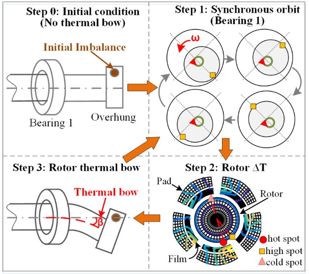
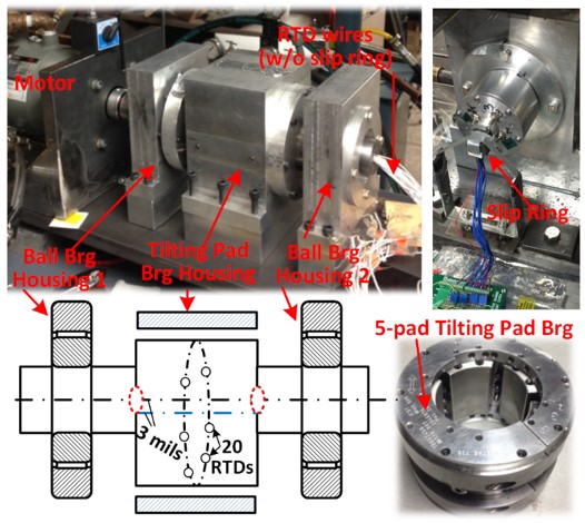
MORTON EFFECT SIMULATION
This code was developed by Dr. Palazzolo and his former students Drs. Jung Gu Lee, Junho Suh and Xiaomeng Tong and his present Phd student Dongil Shin. This code utilizes efficient numerical integration algorithms to simulate the synchronous instability known as the Morton effect. Coupled rotordynamics and fluid film bearing equations are solved to predict the rotor, pad and film temperatures and vibrations of an arbitrary shaft and bearing model with single or double overhung discs. Variable viscosity Reynolds and 3D energy equations are solved at each time step to obtain the temperatures and pressures in the lubricant film, pads/bearing and rotor. Thermally induced rotor bow and its dynamic effects are calculated throughout the simulation.The rotor model may have any number of nodes and includes Timoshenko beam elements and gyroscopic effects. Data is entered through a dedicated Excel based GUI. The code has been employed to assist many TRC members and has been benchmarked with the TRC Morton test rig shown below.
HIGH FIDELITY TILTING PAD JOURNAL BEARING DYNAMIC CO-EFFICIENTS
NONLINEAR MAGNETIC BEARING ROTORDYNAMICS
This code was developed by Dr. Palazzolo and his former students Drs. Zhiyang Wang and Wan Zhong and his present Phd student Xiao Kang. The code provides rotordynamic simulation RS capability along with magnetic bearing actuator component design. The RS model includes not only a generic Timoshenko beam element rotor model but also frequency dependent (Transfer function) feedback loop components: sensors, servo power amplifiers, actuators, etc. for predicting closed loop system imbalance response, stability, natural frequencies, mode shapes, etc. Saturation in the actuator materials and in the power amplifiers and actuators may also be included. The magnetic actuator design feature of the code is applicable for designing both heteropolar and homopolar magnetic bearings. The actuator parameters can be determined by a built in Genetic Algorithm based search routine. The code also has a catcher (auxiliary) bearing modeling feature to predict the number of drops to failure based on ball bearing inner race fatigue. The code has been employed to assist many TRC members and has been benchmarked with the TRC Catcher Bearing test rig shown below.
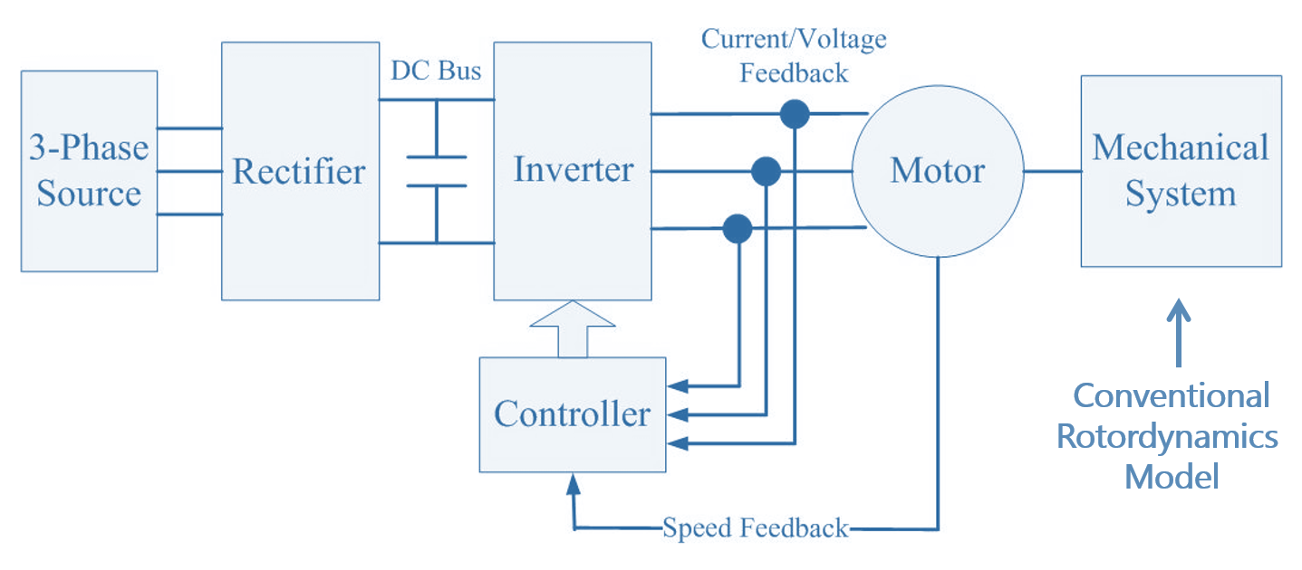
COUPLED LATERAL – TORSION ROTORDYNAMICS WITH VFD
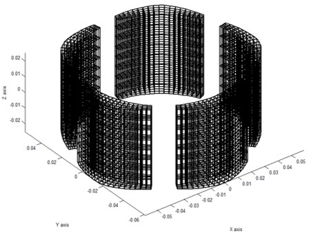
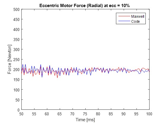
MOTOR LATERAL MAGNETIC STIFFNESS AND FORCE
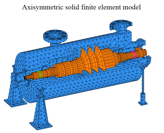
SOLID MODEL DEFINED ROTORDYNAMICS SIMULATION
NONLINEAR ROTORDYNAMICS SIMULATION
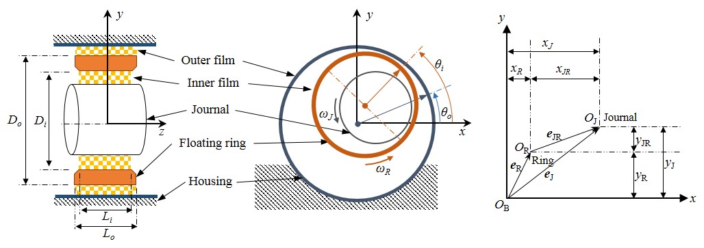
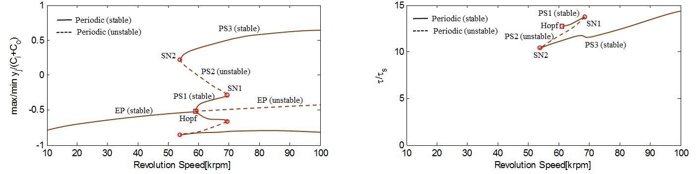
This code was developed by Dr. Palazzolo and his former student Dr. Sitae Kim and his present Phd student Dongil Shin. The code models a generic rotor with Timoshenko beam elements and nonlinear support elements such as floating ring bearings, tilt pad journal bearings, gears, etc. Advanced shooting and arc length continuation algorithms are employed to yield multiple coexisting solutions CS including limit cycles, quasiperiodic and chaotic motions. Support motion inputs are available to investigate jump behavior between CS.
CFD PRE-FILES
Dr. Palazzolo’s group conducts TRC research in several area involving CFD models using CFX or Fluent. TRC members are provided with Tutorials and related Pre-Files that contain the CFD code inputs for the examples in the annual report tutorials.
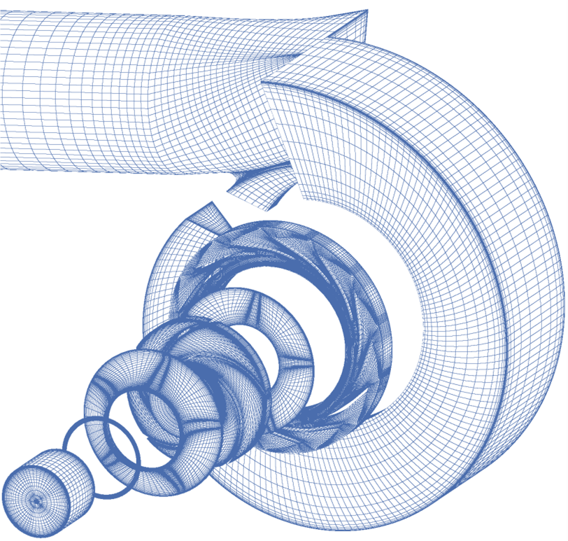
CFD Modeling of Pump and Compressor Impeller and Seal Flows
The objective is to accurately predict stiffness, mass and damping coefficients and impedance curves due to fluid – structure interactions in the primary and secondary flow paths (Former student Dr. Eunseok Kim and Present PhD student Farzam Mortazavi).
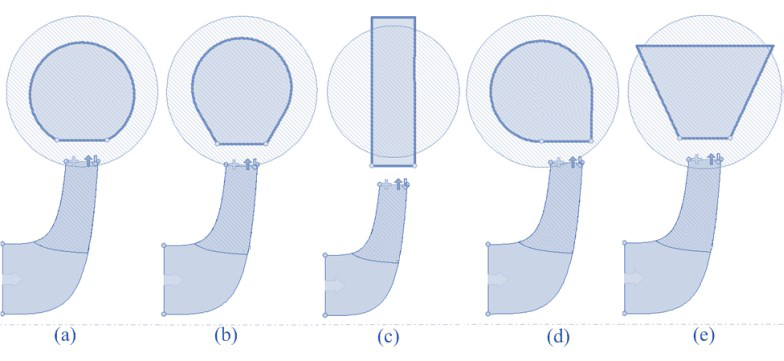
CFD Modeling of Tilting Pad Journal Bearings and Textured Surface Journal Bearings

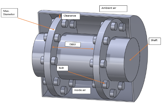
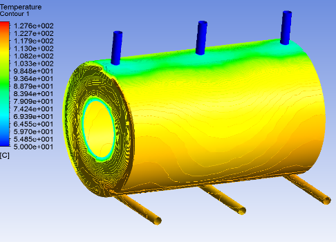
CFD Modelling of Machinery Couplings
The objective is to develop accurate means to predict windage power loss in high speed couplings and peak temperature on coupling guards, as well as to develop means to reduce these temperatures according with API standard recommended limits. (Former student Tianbo Zhai and present students Joseph Oh and Ahmad Dawahdeh)